Current condition
Use approved drawings and labelled samples to show each reference and its normal variation. Mark the leading end and required rotational position, if any, together with dimensions or features that the receiving tool relies on.
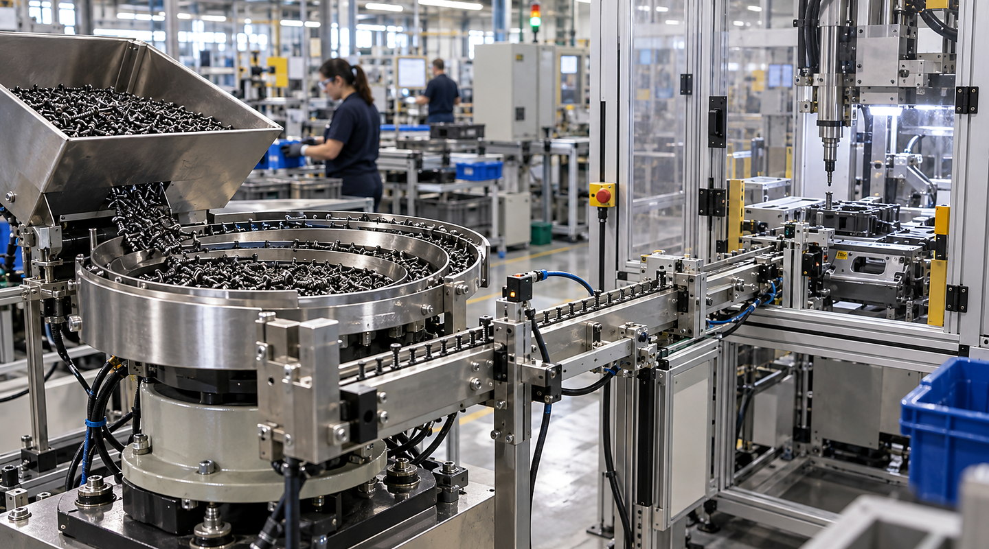
How should component geometry and variation for threaded-insert feeding for assembly be investigated before specifying threaded insert feeders?
An insert family is defined by more than thread size. Record length, outer profile, flange, slot, knurl and end features, then identify which features govern orientation, tooling contact and acceptance at the receiving tool. Carry those distinctions into the sample and interface brief.
For bulk presentation using threaded-insert feeding for assembly, describe the realistic range and how changes in component geometry and variation for threaded-insert feeding for assembly affect the result you need.
Plan threaded insert feeders around real component variation, bulk condition, orientation, usable delivery rate and the downstream interface. Discuss representative part trials with Sorting Solutions. Use this guide to resolve component geometry and variation for threaded-insert feeding for assembly before it limits the final system.
Discuss your application
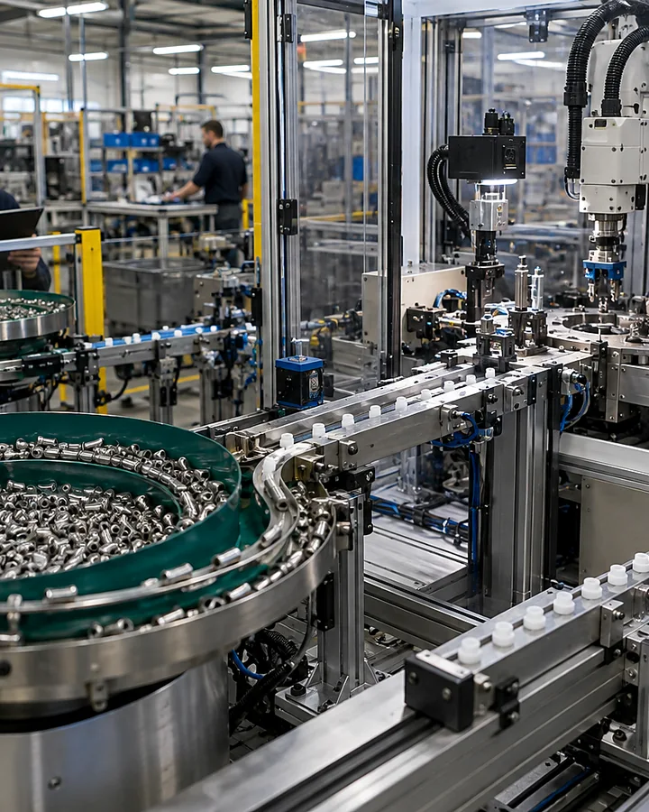
Use approved drawings and labelled samples to show each reference and its normal variation. Mark the leading end and required rotational position, if any, together with dimensions or features that the receiving tool relies on.
Include supplier and batch variation, ordinary finish and residues where relevant. Keep accepted samples distinct from damaged or suspect examples so the trial records which condition was presented and what response was expected.
Map each meaningful geometry change to orientation, permitted contact, nesting risk, single-part release and final support. Identify distinctions that tooling can exclude and those requiring a separate identification decision; do not infer identity from presence alone.
For Component Geometry and Variation for Threaded-Insert Feeding for Assembly: Component sample trial, describe the current position, required outcome, acceptable limits and known exceptions for component geometry and variation for threaded-insert feeding for assembly. That lets us compare options against your real production rather than one nominal value.
For Component Geometry and Variation for Threaded-Insert Feeding for Assembly: Component sample trial, describe the current position, required outcome, acceptable limits and known exceptions for surface, fragility and entanglement behaviour. That lets us compare options against your real production rather than one nominal value.
For Component Geometry and Variation for Threaded-Insert Feeding for Assembly: Component sample trial, describe the current position, required outcome, acceptable limits and known exceptions for bulk condition and replenishment method. That lets us compare options against your real production rather than one nominal value.
For Component Geometry and Variation for Threaded-Insert Feeding for Assembly: Component sample trial, describe the current position, required outcome, acceptable limits and known exceptions for required orientation and delivery rate. That lets us compare options against your real production rather than one nominal value.
For Component Geometry and Variation for Threaded-Insert Feeding for Assembly: Component sample trial, describe the current position, required outcome, acceptable limits and known exceptions for escapement and downstream pick interface. That lets us compare options against your real production rather than one nominal value.
For Component Geometry and Variation for Threaded-Insert Feeding for Assembly: Component sample trial, describe the current position, required outcome, acceptable limits and known exceptions for jam, damage and recovery acceptance checks. That lets us compare options against your real production rather than one nominal value.