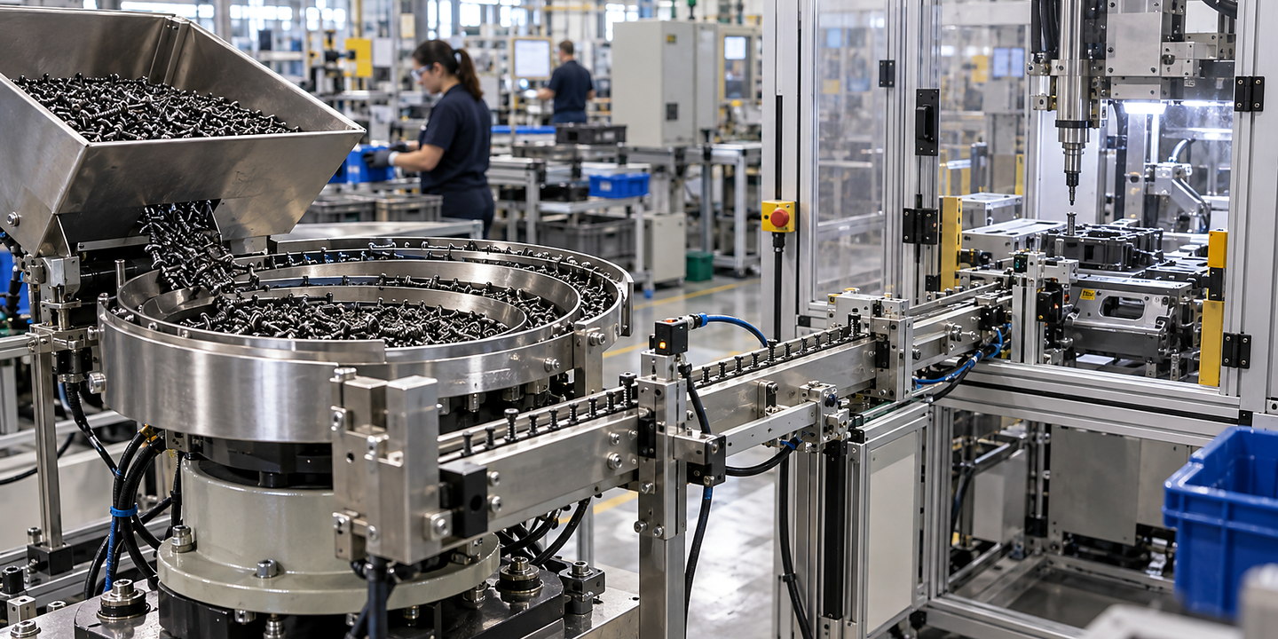
Plan mechanical, electrical, control, data, safety and operator interfaces for threaded insert feeders.
In brief
The insert feeder and receiving tool need a shared definition of demand, readiness, release and occupancy. Specify the hand-off position and support, then agree what happens when a cycle stops with an insert in transit or already at the tool. Link those states to the metered-delivery requirements.
For flexible or metered delivery involving threaded-insert feeding for assembly, define every physical connection, signal, responsibility, check and fallback before installation.
On the production floor
Connect equipment, controls and people into one reliable process — Threaded Insert Feeders
Plan threaded insert feeders around real component variation, bulk condition, orientation, usable delivery rate and the downstream interface. Discuss representative part trials with Sorting Solutions. Your integration review should connect bulk condition and replenishment method, required orientation and delivery rate and the people who run the process.
Six areas to coordinate for threaded insert feeders
Mechanical
Show the insert pose and permitted contact at discharge, along the transfer route and at the receiving tool. Agree support until the tool takes control, alignment references and access for the documented intervention and maintenance methods.
Electrical
For Threaded Insert Feeders, list the supplies, isolation, protective devices, panels and cable routes required by the proposed installation.
Controls
Assign responsibility for call-for-part, ready, occupied and cycle-complete states where required. Record the response to missing confirmation or interruption after release; the two machines must resolve the existing insert before requesting another.
Safety
Review risk controls, stop behaviour, access, reset and the checks needed around required orientation and delivery rate.
Data
Associate insert references with approved tooling, settings or recipe revisions where applicable. Agree which delivery, exception and changeover records are needed; neither a timestamp nor a part-present signal proves insert identity without the defined checks.
Your team
Define responsibilities for replenishment, clearing residual inserts at a reference change, documented recovery and first accepted restart. Retain the accepted sample set and tooling identification so the approved arrangement can be reproduced.
How the work comes together
Plan fault recovery for bulk presentation using threaded-insert feeding for assembly as carefully as normal running
For Threaded Insert Feeders, your team can review each stage before the complete installation is put into routine use.
01
Review Representative Production Components
Share representative production components and the downstream interface, including the normal range for component geometry and variation for threaded-insert feeding for assembly and the difficult surface, fragility and entanglement behaviour cases.
02
Trial Separation, Orientation and Presentation
Compare suitable methods and use focused trials to show how each option performs against bulk condition and replenishment method.
03
Develop Tooling, Controls and the Downstream Interface
Connect the equipment to your line, services and controls while resolving required orientation and delivery rate for day-to-day operation.
04
Challenge Delivery, Replenishment, Jams and Recovery
Confirm escapement and downstream pick interface, then complete and record jam, damage and recovery acceptance checks before your operating team takes over.
For your application: check bulk condition and replenishment method, required orientation and delivery rate, escapement and downstream pick interface, and jam, damage and recovery acceptance checks as part of the complete line trial.
Important limits
Line connections can change the approach for Threaded Insert Feeders
Sample trials must include normal, marginal and supplier-variant components.
Quoted feeder output is not the same as usable delivery at the downstream process.
Fragile, flexible, magnetic or entangling parts may need a different presentation method.